


Share with:
A Pulse-Doppler radar is a radar system that determines the range to a target using pulse-timing techniques, and uses the Doppler effect of the returned signal to determine the target object’s velocity. It combines the features of pulse radars and continuous-wave radars, which were formerly separate due to the complexity of the electronics.
The first operational Pulse Doppler radar was in the CIM-10 Bomarc, an American long range supersonic missile powered by ramjet engines, and which was armed with a W40 nuclear weapon to destroy entire formations of attacking enemy aircraft. Pulse-Doppler systems were first widely used on fighter aircraft starting in the 1960s. Earlier radars had used pulse-timing in order to determine range and the angle of the antenna (or similar means) to determine the bearing. However, this only worked when the radar antenna was not pointed down; in that case the reflection off the ground overwhelmed any returns from other objects. As the ground moves at the same speed but opposite direction of the aircraft, Doppler techniques allow the ground return to be filtered out, revealing aircraft and vehicles. This gives pulse-Doppler radars “look-down/shoot-down” capability. A secondary advantage in military radar is to reduce the transmitted power while achieving acceptable performance for improved safety of stealthy radar.
Pulse-Doppler techniques also find widespread use in meteorological radars, allowing the radar to determine wind speed from the velocity of any precipitation in the air. Pulse-Doppler radar is also the basis of synthetic aperture radar used in radar astronomy, remote sensing and mapping. In air traffic control, they are used for discriminating aircraft from clutter. Besides the above conventional surveillance applications, pulse-Doppler radar has been successfully applied in healthcare, such as fall risk assessment and fall detection, for nursing or clinical purposes.
History
The earliest radar systems failed to operate as expected. The reason was traced to Doppler effects that degrade performance of systems not designed to account for moving objects. Fast-moving objects cause a phase-shift on the transmit pulse that can produce signal cancellation. Doppler has maximum detrimental effect on moving target indicator systems, which must use reverse phase shift for Doppler compensation in the detector.
Doppler weather effects (precipitation) were also found to degrade conventional radar and moving target indicator radar, which can mask aircraft reflections. This phenomenon was adapted for use with weather radar in the 1950s after declassification of some World War II systems.
Pulse-Doppler radar was developed during World War II to overcome limitations by increasing pulse repetition frequency. This required the development of the klystron, the traveling wave tube, and solid state devices. Early pulse-dopplers were incompatible with other high power microwave amplification devices that are not coherent, but more sophisticated techniques were developed that record the phase of each transmitted pulse for comparison to returned echoes.
Early examples of military systems includes the AN/SPG-51B developed during the 1950s specifically for the purpose of operating in hurricane conditions with no performance degradation.
The Hughes AN/ASG-18 Fire Control System was a prototype airborne radar/combination system for the planned North American XF-108 Rapier interceptor aircraft for the United States Air Force, and later for the Lockheed YF-12. The US’s first pulse-Doppler radar, the system had look-down/shoot-down capability and could track one target at a time.
Weather, chaff, terrain, flying techniques, and stealth are common tactics used to hide aircraft from radar. Pulse-Doppler radar eliminates these weaknesses.
It became possible to use pulse-Doppler radar on aircraft after digital computers were incorporated in the design. Pulse-Doppler provided look-down/shoot-down capability to support air-to-air missile systems in most modern military aircraft by the mid 1970s.
Principle of Pulse Doppler Radar

 Velocity Measurement

Pulse-Doppler radar is based on the Doppler effect, where movement in range produces frequency shift on the signal reflected from the target.

Signal processing
The signal processing enhancement of pulse-Doppler allows small high-speed objects to be detected in close proximity to large slow moving reflectors. To achieve this, the transmitter must be coherent and should produce low phase noise during the detection interval, and the receiver must have large instantaneous dynamic range.
 Pulse-Doppler signal processing detailed explanation – Pulse-Doppler signal processing also includes ambiguity resolution to identify true range and velocity.
- Ambiguity resolution detailed explanation – The received signals from multiple PRF are compared to determine true range using the range ambiguity resolution process.
- Range ambiguity resolution detailed explanation – The received signals are also compared using the frequency ambiguity resolution process.
- Frequency ambiguity resolution detailed explanation
 Pulse-Doppler signal processing detailed explanation – Pulse-Doppler signal processing also includes ambiguity resolution to identify true range and velocity.
Pulse Doppler Radar - Critical Elements & Functioning

Pulse radar emits short and powerful pulses and in the silent period receives the echo signals. In contrast to the continuous wave radar, the transmitter is turned off before the measurement is finished. This method is characterized by radar pulse modulation with very short transmission pulses (typically transmit pulse durations of τ ≈ 0.1 … 1 µs). Between the transmit pulses are very large pulse pauses Τ >> τ, which are referred to as the receiving time (typically Τ ≈ 1 ms). The distance of the reflecting objects is determined by runtime measurement (at a fixed radar) or by comparison of the characteristic changes of the Doppler spectrum with the values for given distances stored in a database (for radar on a fast-moving platform). Pulse radars are mostly designed for long distances and transmit a relatively high pulse power.
Important distinguishing feature to other radar method is the necessary time control of all processes inside the pulse radar. The leading edge of the transmitted pulse is the time reference for the runtime measurement. It ends with the transition of the rising edge of the echo signal in the pulse top. Systematic delays in signal processing must be corrected when calculating the distance. Random deviations influence the accuracy of the pulse radar.
- Transmit Signal
- Echo Signal
- Design, Block Diagram
- Applications
Transmit Signal
The waveform of the transmitted signal can be described mathematically as:
| s(t) = A(t)· sin[2πf(t)·t + φ(t)] | (1) |

The function A(t) is a variation of the amplitude in the function of time t - ie an amplitude modulation. In the simplest case, the transmitter is for a short time switched on (for the time τ) and remains in the rest of the time in the “off position”. A(t) is then in the transmission case = 1, otherwise = 0. The function of time is then determined by the pulse repetition frequency and the duty cycle. Since the radar returns are subject to various losses, an actual amplitude modulation makes little sense except for just this switching function (On/off keying). The envelope of the frequency spectrum of a sequence of rectangular pulses is represented by a (sin x)/x function. The essential parts of the transmission power (note the logarithmic scale of the ordinate in Figure 3) are in a region BHF = 2/τ in the vicinity of the transmission frequency ftx.
The pulse repetition frequency fPRF and the duration of the transmitted pulse τ and the receiving time (Τ − τ) have an influence on the performance of the radar, e.g. the minimal measuring range (the transmit pulse must have completely exited the antenna) and the maximum unambiguous range (the echo signal must be received in the time before the next transmission pulse).
The duration of the transmit pulse τ substantially affects the range resolution ΔR of pulse radar. The range resolution is:
| ΔR = 0.5·τ·c | (2) |
The shorter the transmission pulse, the closer one behind the other two reflectors may be positioned so as to be nevertheless detected as two reflectors and not as one large object. The transmitter bandwidth BHF of the pulse radar increases with decreasing pulse width:
| BHF = τ−1 | (3) |
The shortening of the pulses limits the maximum range in the case of simple pulse modulation. Under these conditions, the pulse energy Ep can be increased only by the pulse power PS at a required range resolution.
For the maximum range of the pulse radar, the pulse energy is crucial, and not its pulse power:
| Ep = Ps· τ = Pav· Τ = | Pav | where | Ep = energy content of the pulse PS = transmission pulse power Pav = average power | (4) |
| fPRF |
Significant improvements in this situation can be achieved with the internal modulation of the transmit pulse (intra-pulse modulation). The relationship between the duration of the transmit pulse and the duration of the received pulse is resolved by the pulse compression in the receiver. A location of various reflectors and the measurement of its individual range can also be carried out within the duration of the transmit pulse.
The function φ(t) in equation (1) is the expression for a phase shift of the whole signal. The initial phase of the transmitted signal can either be known and can be predictable (due to the generation of oscillation). In this case, the pulse radar is attributable to the fully coherent radars. The actual phase angle can also be known but the initial state can be unpredictable. Then the radar is one of the pseudo-coherent radars. If this initial phase completely indeterminate (chaotic), then the radar is one of the non-coherent radars. Only with a possible phase-encoded Intra Pulse modulation, this function gets more importance.
Echo Signal
Usually, it is assumed that the duration of the transmitted pulse is equal to the duration of the reflected echo pulse. Thus, in the ratio of the transmitted power and the received power (which is used in the fundamental radar range equation) can be dispensed with a time specification.
- By the reflection of the transmit signal the spectrum may be modified:
- It can occur additional harmonics to the carrier frequency.
- The carrier frequency can be imposed on one or more Doppler frequencies.
- The direction of the polarization can be changed.
- The pulse duration of the echo signal is not constant. The duration of the reflected pulse can be considerably stretched by interference from reflections at areas with slightly different distances (and following different run times).
All together: the echo signal is subject to so many influences that the waveform and the shape of the echo signal in the result must be regarded as unknown. Nevertheless, in order to build an optimal matched receiver or an optimal matched filter, multiple receiving channels must be set up in parallel, taking into account all the possible deformations of the signal. In a selection circuit, the echo signal with the best (greatest-of) Signal to Noise Plus Interference Ratio (SNIR) is then further processed. The “position” of the greatest-of-switch is also saved as important information for the identification of this echo signal.
In general, the receiving bandwidth is kept as small as possible, so not much unnecessary noise is received. Therefore, to select the bandwidth only with BHF = 1/τ for a simple pulse radar. The influence of the noise can be suppressed in the receiver using of pulse integration. Here, a sum of pulse periods is formed. The reflecting object is assumed to be stationary during the time of these pulse periods. Since the noise is randomly distributed, thereby the sum of the noise cannot reach the sum of the echo signals. The signal-to-noise ratio is improved by this measure.
 Critical Components
 Critical Components
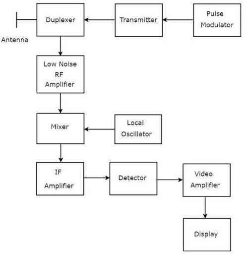
- Synchronizer
- Modulator
- Transmitter
- Duplexer
- Antenna
- Receiver
- Display
The construction of a pulse radar depends on whether transmitter and receiver are at the same site (monostatic radar) or whether both components are deployed at completely different locations (bistatic radar).
A monostatic pulse radar, in addition to the compact design has the advantage that the important for pulse radars timing devices can be concentrated in a central synchronization block. Internal runtimes of the radar triggers can thus be kept low. An elaborate radar antenna can be used by means of a multiplexer for both transmitting and receiving.
The disadvantage is that often the highly sensitive radar receiver must be switched off by a duplexer for its own protection against the high transmission power. During this time it cannot receive anything.
In a bistatic pulse radar, the receiver is equipped with its own antenna in a different location as the transmitter. This has the advantage that the receiver can operate without significant protective measures against to a high transmission power. In the simplest case, a network is constructed from extra receiver locations to an existing monostatic pulse radar. Example given: weather radar Poldirad in Oberpfaffenhofen, Germany (near Munich). The receiving antennas are not very directionally: they must be able to receive from several directions simultaneously. The disadvantage here is the very complex synchronization. Simultaneously with the echo signals, the receiver must also receive the direct transmission signal. From this signal and the known distance to the transmitter, a sync signal must be generated. Principal military application of bistatic configurations are the Over-The-Horizon (OTH) Radars.
The passive radars are a variant of the bistatic radar. They parasitically use a variety of RF emissions (radio or television stations, or external pulse radars) The passive radar calculates the position of the targets from the difference between the time of the direct path of the signal and the additional running time of the reflected echo signals. Ambiguities in the measurement can be excluded on the one hand by direct direction finding involving spurious emissions of the target or by synchronization of two passive radars working at different locations.
The global Doppler radar market is expected to rise from a valuation of USD 7,800 million in 2017 to USD 9,984 million by 2023 at a CAGR of 4.20% from 2018 to 2023 (forecast period).Future Research Trends and Challenges
The progress and development of radar technology cannot be separated from the promotion of multidisciplinary basic research, such as optics, measuring means, imaging, experimental observation, algorithm improvement, and model optimization.
Multidisciplinary radar design and optimization not only considers the coupling design between disciplines but also is more appropriate to the essence of the problem, so that the radar signal can be high quality and fidelity.
Most multidisciplinary optimizations consider the multiobjective mechanism to balance the interdisciplinary influence and explore the overall optimal solution, which can effectively avoid the waste of manpower, physics, financial resources, and time caused by repeated design. Some radar multidisciplinary optimization can adopt collaborative design and concurrent design, which can shorten the cycle as much as possible.
The progress and development of radar technology cannot be separated from the promotion of multidisciplinary basic research, such as optics, measuring means, imaging, experimental observation, algorithm improvement , and model optimization. Multidisciplinary radar design and optimization not only considers the coupling design between disciplines but also is more appropriate to the essence of the problem, so that the radar signal can be high quality and fidelity. Most multidisciplinary optimizations consider the multi objective mechanism to balance the interdisciplinary influence and explore the overall optimal solution, which can effectively avoid the waste of manpower, physics, financial resources, and time caused by repeated design. Some radar multidisciplinary optimization can adopt collaborative design and concurrent design, which can shorten the cycle as much as possible.
Deeply Expand the Basic Content
With the scientific progress in microwave, computer, semiconductor, large-scale integrated circuit, and other fields, radar technology is developing continuously and its connotation and research content are constantly expanding. Radar function has gradually evolved from a single function to a multitask and multi function radar system. Radar engineering theory is not confined to Shannon theorem whose working frequency, bandwidth, and resolution are improving with the multi functional architecture. The implementation and analysis of the path planning and wavelength are also applied.
Diversification of Signal Processing Technology
In addition to conventional processing methods such as correlated/uncorrelated processing, signal processing technology includes space-time adaptive (STAP), multiple-input multiple-output (MIMO), synthetic aperture (SAR/ISAR/CSAR), synthetic pulse and aperture (SIAR), and adaptive/cognitive radar signal processing technology based on artificial intelligence.
Classification of Detection Techniques
The corresponding detection means are also varied for differentiated waveforms of radar signals. Multiple technology methods of wavelet-based transform, clutter detection, algorithmic improvement, time-frequency, and phase-coded are applied to detect the radar signal, which can reduce signal divergence and attenuation dramatically. The work done can effectively help promote the stability of radar signal which is essential to image resolution of coherent imaging, data transmission, and radar receive.
Challenges
Significant changes have taken place in the targets observed by radar, and the electromagnetic environment of radar work has deteriorated seriously, which has a tremendous impact on the development of radar.
New Challenges in the Used Environment
Ground radars are difficult to detect and early warn from a long distance because of the observation dead angle, strong ground clutter background, and much higher flight speed than ground vehicles. The harsh electromagnetic environment of strong electronic jamming in the future, as well as the discovery, recognition, and confirmation of high-speed, invisible targets (cruise missiles) and camouflage, concealment and deception CCD targets in the background of severe ground and sea clutter, makes it difficult for the original centralized launching mechanical scanning radar to meet these new requirements.
Active Phased Array Radar Technical Requirement
Active phased array radar needs a large number of T/R components whose performance, weight, size, and cost of T/R components are important considerations for the whole AESA system. The phase shifter, attenuator, amplifier, preamplifier driver stage, switch, and control circuit are all integrated in a single circuit with only about 4~5mm2 chip of the multifunctional core which is limited by chip development technology.
Heat Dissipation of Radar System
Radar system is a complex and multifunctional integrated system. Data processing is carried out at all times. This way of work will generate a lot of heat. The problem of heat dissipation of multifunctional radar system needs to be solved urgently. Some heat dissipation techniques can be tried and applied, such as heat pipe heat dissipation. and establishment and development of heat management system.
Comments (1 Comment)


Leave a Reply to Fermin Cancel reply